 In the early 90’s I was approached to design and build Exhaust Gas Recirculation (EGR) systems for very important diesel engine exhaust emissions research. For decades, the EPA and other government air quality agencies around the world have been tightening the emissions regulations. And the reductions in both particulate matter (PM) and oxides of nitrogen (NOx) have been severe. It is incredibly difficult to achieve these very strict and ever-tightening exhaust emissions targets.
There was a research consortium formed to conduct fundamental research of the effects of exhaust gas recirculation in diesel engines. This was the first real, hardcore look into EGR’s effect on exhaust gas emissions. The consortium was available by annual subscription; pay the money, receive reports that detailed the exhaustive research (great pun!). To my belief, the majority of the diesel engine manufacturers in the world were members. The results of my work, my hardware, were then taken by each individual company into their labs to implement their own EGR concepts for production in their engines. It was my efforts that led the world into the age of EGR systems on heavy-duty diesel engines!
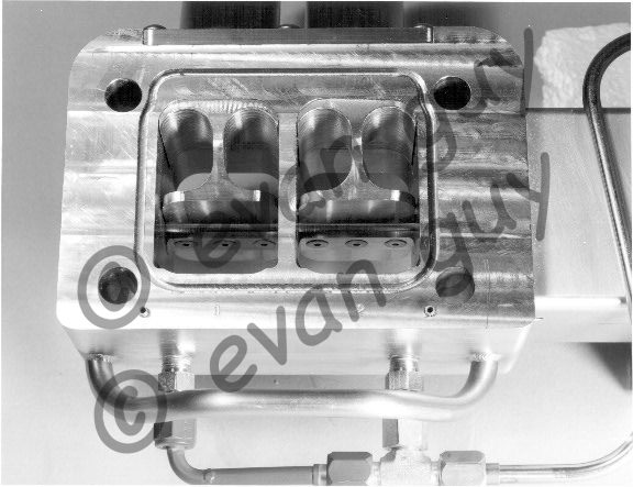
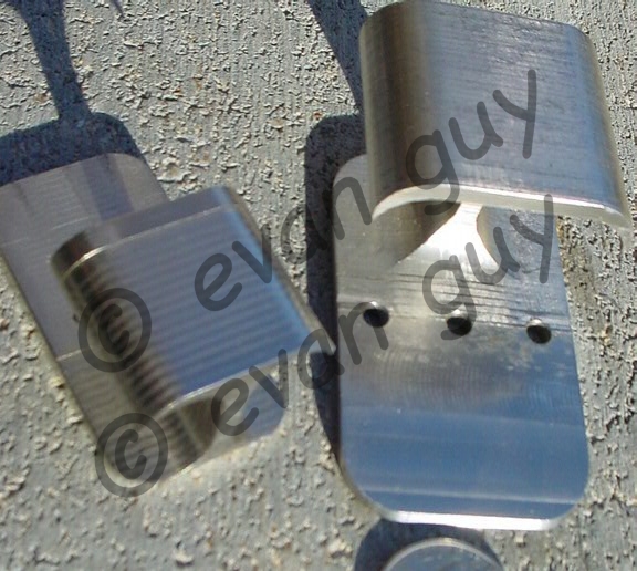
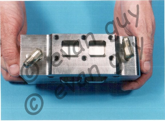
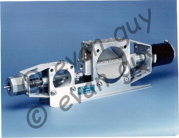
I designed and built two distinctly different types of EGR systems. Initially, I was directed to do the Low Pressure Loop system (first 2 pictures). Low pressure loop means that the exhaust throttling valve was located AFTER the turbine in the turbocharger and the intake throttling valve was BEFORE the compressor of the turbo. Throttling is needed to achieve pressure differentials required to divert exhaust gas flow from the exhaust stream, through a heat exchanger, and back into the inlet air stream.
After the research organization thoroughly tested the servo-controlled ‘low pressure loop’ valves, they came back to me and said their results indicated that HPL valves (High-Pressure Loop) valves were likely the way to go. This required a new design approach. The exhaust gas temperature is hundreds of degrees higher before the exhaust turbine that after. This also meant that the valve would need to be between the exhaust manifold and the turbocharger. During high-output conditions, the exhaust manifold and turbocharger can begin to glow a dull red. I think exhaust gas temperature approached 1,250+ deg F.
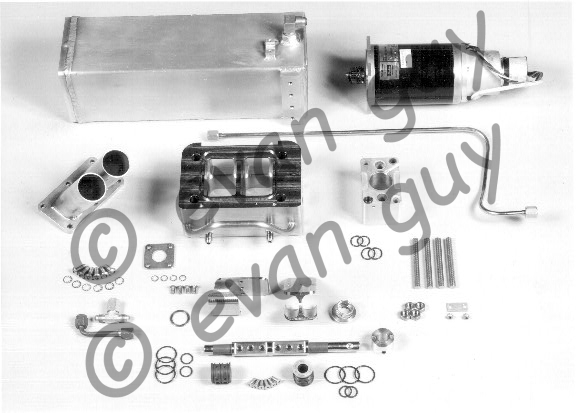
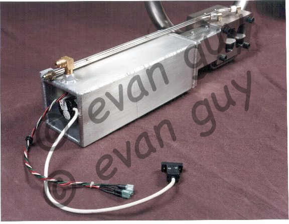
So now my stuff needed to be tucked into this violently-vibrating-and-burning-freaking-HOT place!! These valves were controlled by electronic servo motors, with delicate position encoders. The first order of business was to enclose the servo/encoder withing a liquid-cooled environment. That’s the long square aluminum box (hollow and liquid-cooled) that’s visible in the photos. The guys in the engine lab named it “the mailbox”. It was forever known as such! All of this stuff is seeing super high temperatures. My clever design has careful water coolant flow through the whole system, yet simple in practice. One cooling hose in, one cooling hose out, and two electrical plugs inside the mailbox.
The water cooling was directed into the end of the EGR valve, through the shaft bearing, all around the O-ring seals, through the throttle shaft to the bearing on the opposite side, then through the mailbox, and out. This worked beautifully!
Never satisfied, they came back to me after LOTS of testing and said, “our air-fuel ratios are are a couple of points lower with the valve, than without. That’s making the engine run richer, producing higher particulate (PM) and NOx”. The cause of this turbo boost degradation is the volume that was added to the exhaust system. The exhaust energy that is imparted to the turbine of the turbocharger has 2 components. There’s the bulk flow at its average flow rate. There is ALSO the “blow-down energy”–that’s the instantaneous energy impulse that occurs when the exhaust valve opens. With my EGR system, the volume of the diversion conduits rob the turbocharger of the blow-down impulse energy. The blow-down isn’t right next to the turbine–there’s a bunch of volume in the Y-pipe that absorbs the impulse.
I went home and slept on it. I came up with the 3-way EGR valve! When the valve is wide open, there is a “wing” up high that blocks the EGR passage’s volume, restoring the turbo performance! The staff in the lab soon named the neat butterfly blades, “the BatWing Butterfly”! That forever stuck. The “mailbox” and the “batwing butterfly”! BTW, we got a patent on the BatWing deal: http://patft.uspto.gov/netacgi/nph-Parser?Sect1=PTO1&Sect2=HITOFF&d=PALL&p=1&u=%2Fnetahtml%2FPTO%2Fsrchnum.htm&r=1&f=G&l=50&s1=5740785.PN.&OS=PN/5740785&RS=PN/5740785
All of this stuff survived literally thousands of hours of brutal, super hot, super vibrating testing. It worked exactly as designed and produced fantastic results!